

Details
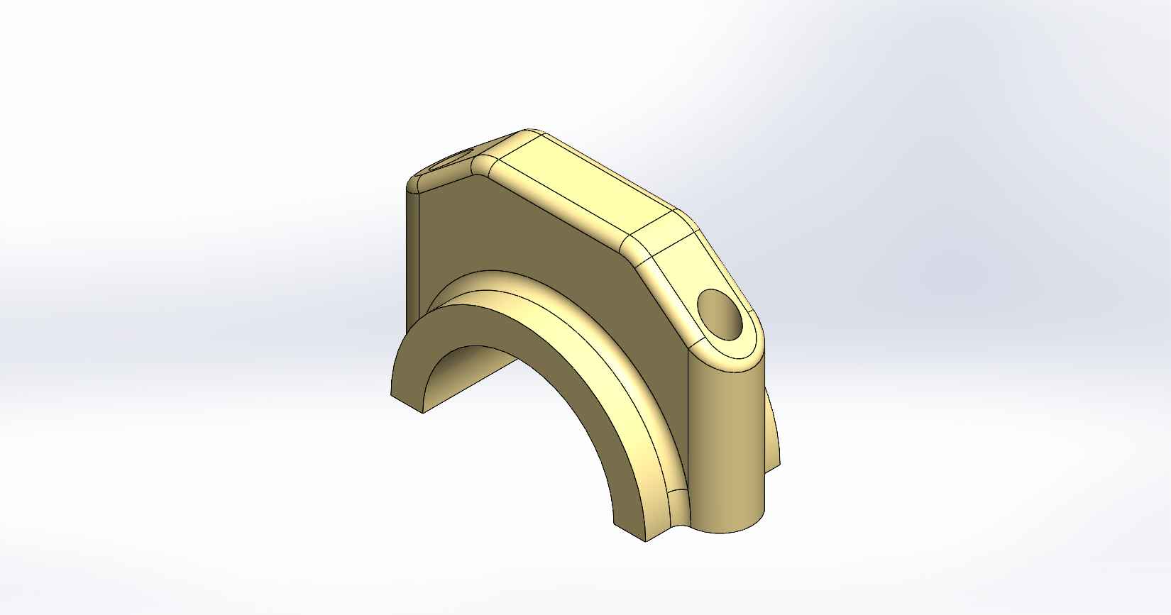
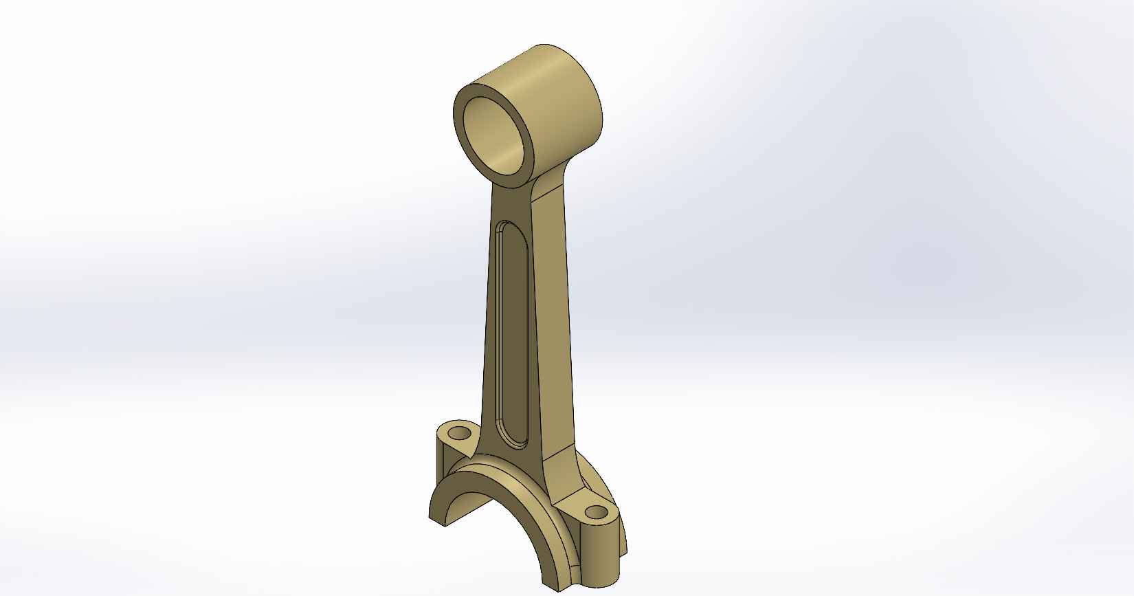
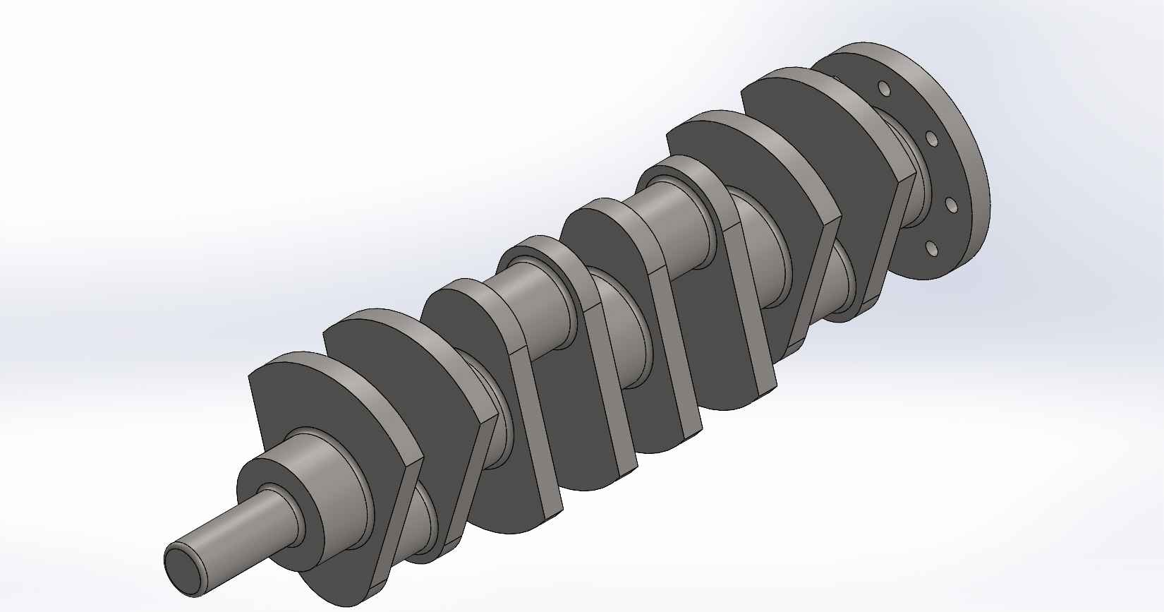
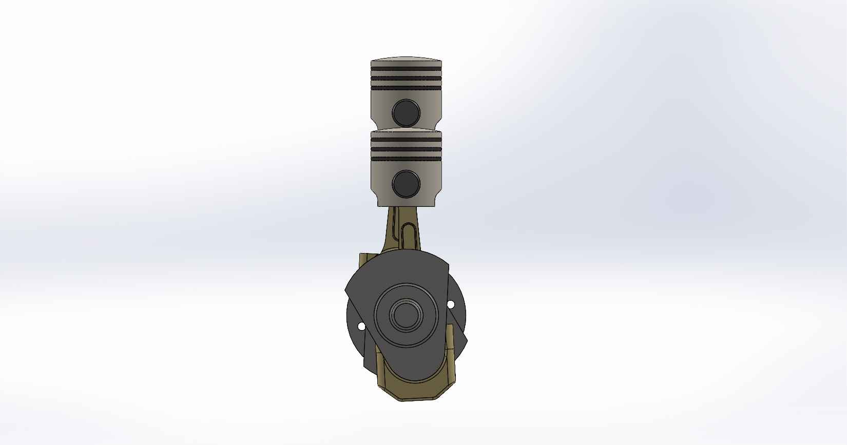
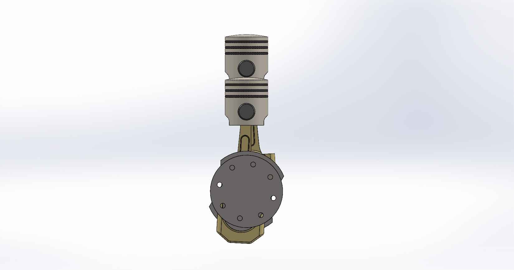
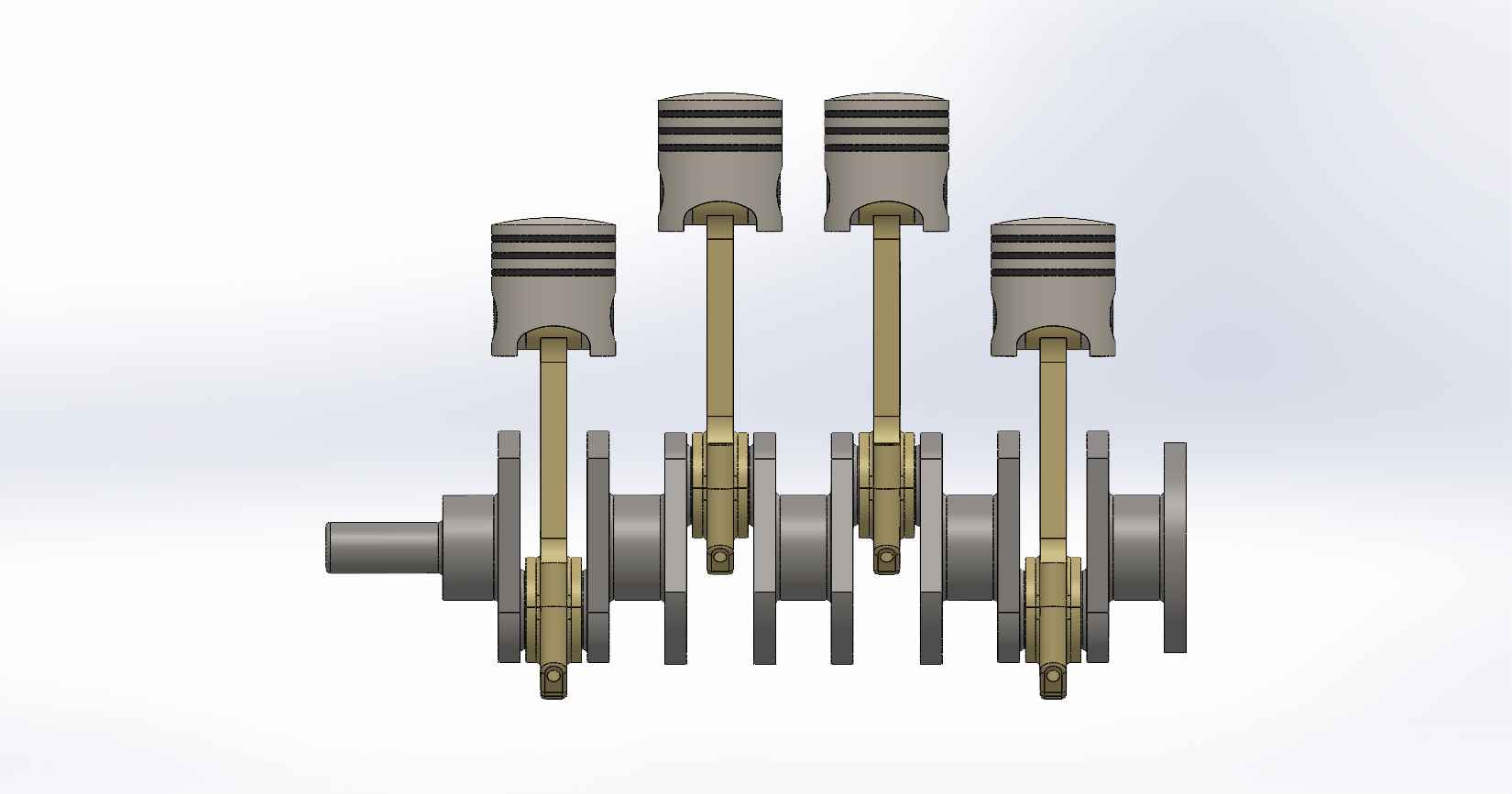
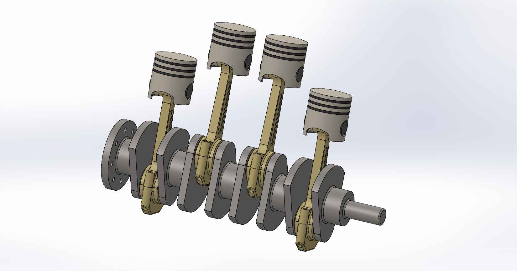
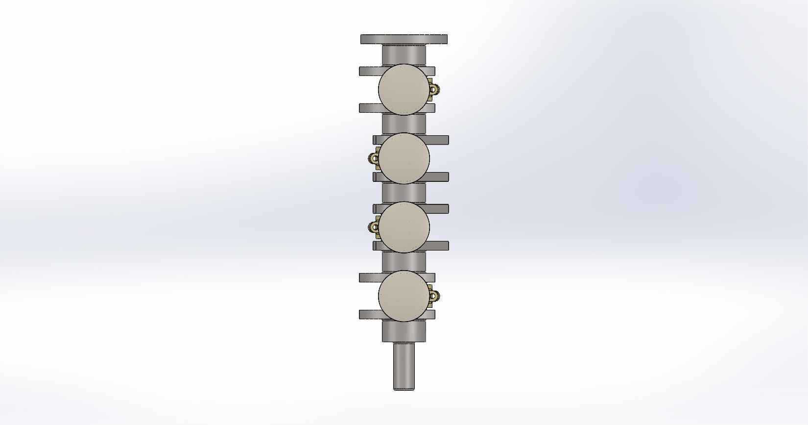
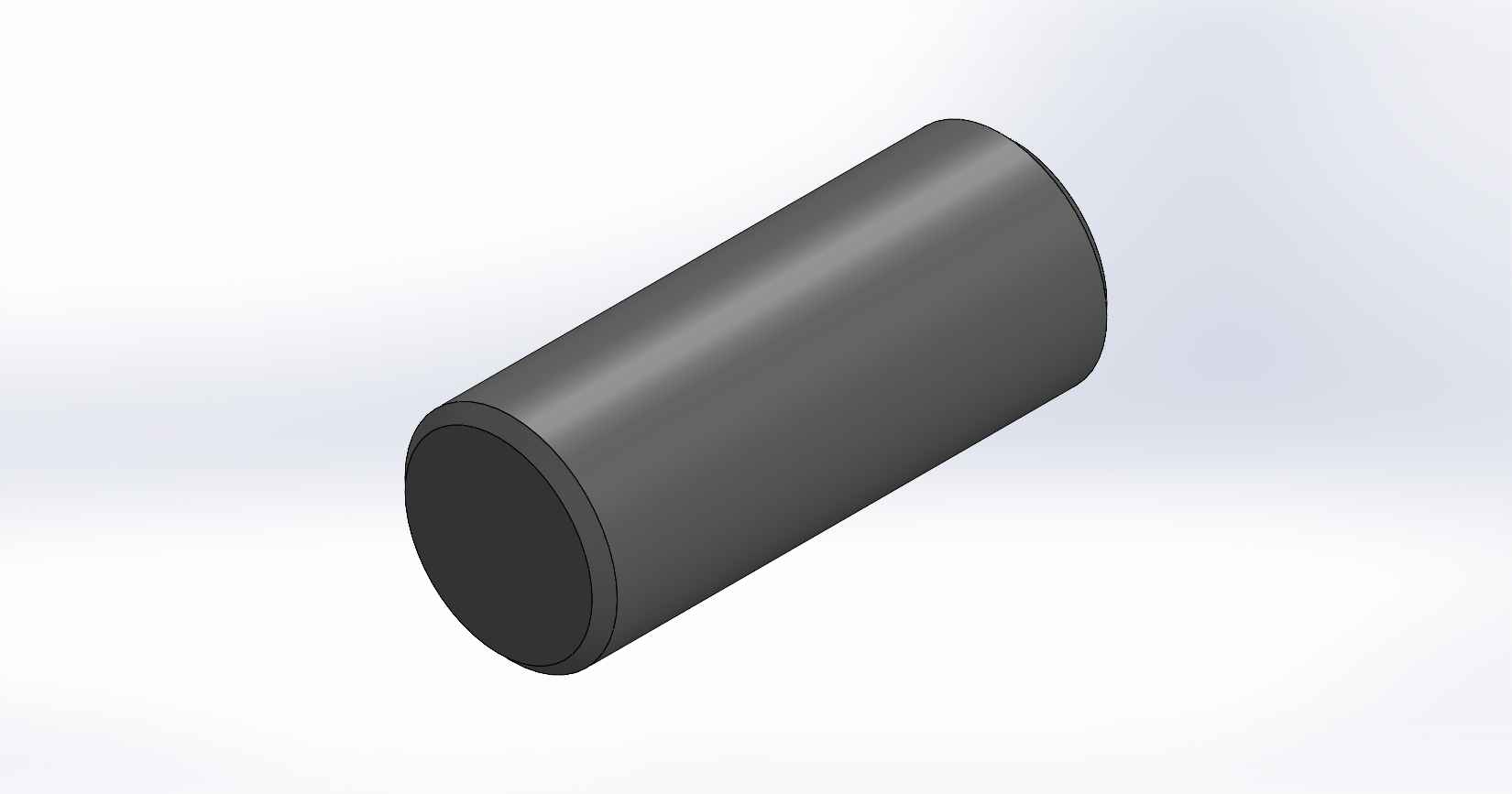
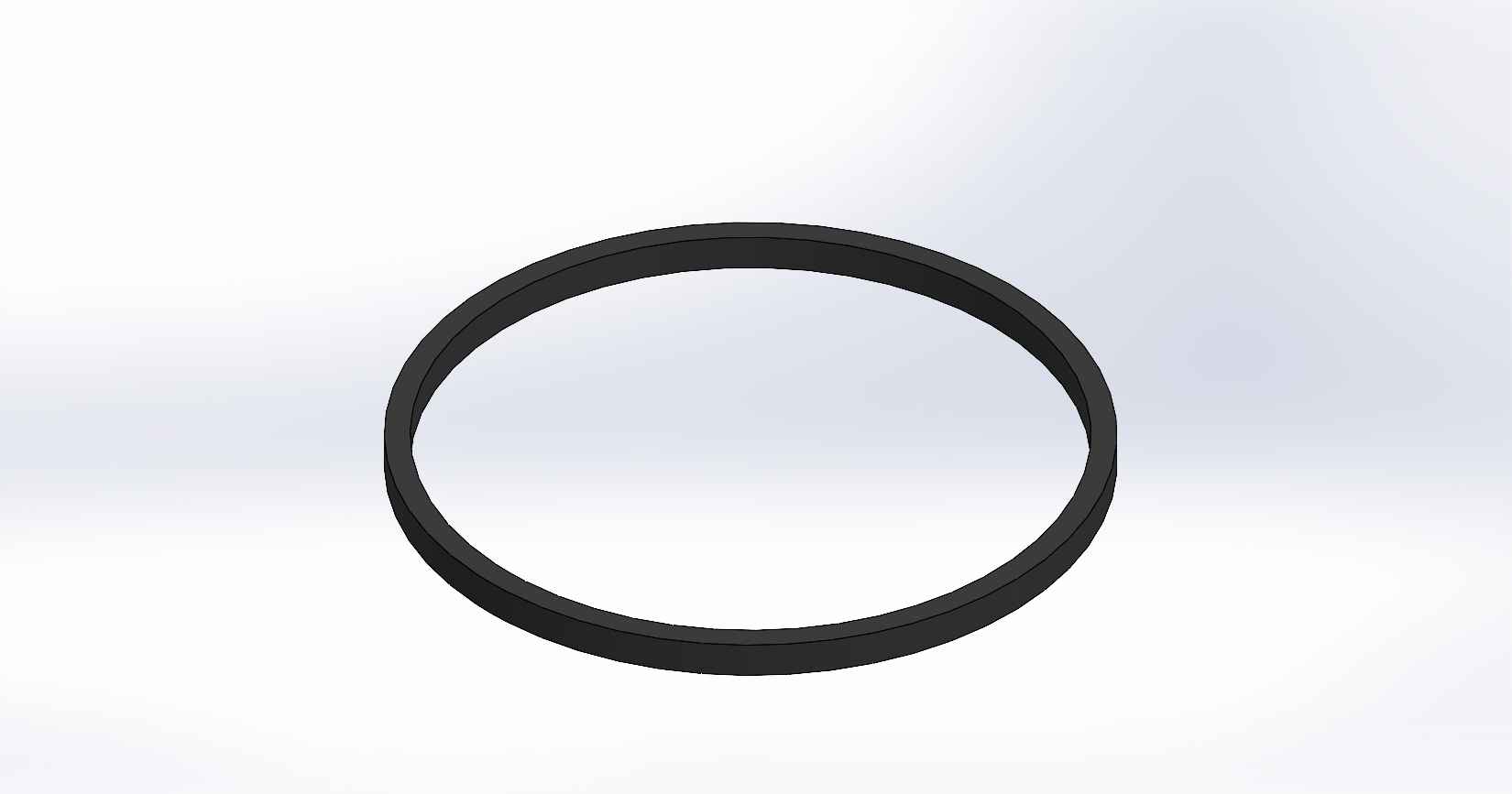
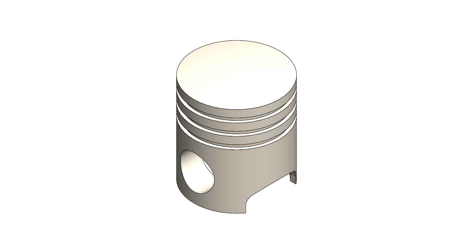
A four-stroke engine is a type of internal combustion engine commonly used in automobiles, motorcycles, and other vehicles. It consists of various parts that work together to convert fuel into mechanical energy. Here is a description of the key parts and assembly of a four-stroke engine, using SolidWorks as the design software. Piston: The piston is a cylindrical component that fits inside the engine cylinder. It moves up and down within the cylinder as a result of the combustion process. The piston is typically made of aluminum alloy and has piston rings installed around its circumference to create a seal between the piston and the cylinder wall. Piston Pin: The piston pin, also known as the wrist pin, is a cylindrical metal pin that connects the piston to the connecting rod. It allows the piston to pivot on the pin as it moves up and down within the cylinder. The piston pin is typically made of hardened steel and is secured in place with retaining clips or circlips. Piston Rings: Piston rings are metallic rings that are installed around the outer circumference of the piston. They ensure a proper seal between the piston and the cylinder wall, minimizing gas leakage and maintaining compression. There are typically three types of piston rings: compression rings, oil control rings, and scraper rings. Crankshaft: The crankshaft is a central rotating shaft that converts the reciprocating motion of the pistons into rotary motion. It is made up of multiple sections known as journals and throws. The connecting rods are connected to the throws of the crankshaft. The crankshaft is typically forged from high-strength steel and precisely balanced to minimize vibrations. Connecting Rod: Connecting rod, also called con rod, connect the piston to the crankshaft. They transmit the linear motion of the piston to the rotary motion of the crankshaft. Connecting rods are usually made of forged steel or aluminum alloy for high strength and durability. They have bearings at both ends to provide smooth movement. Connecting Rod Cap: Connecting rod cap are detachable covers that secure the connecting rods to the crankshaft. They are typically separate components that bolt onto the lower end of the connecting rods. The connecting rod caps are carefully aligned and torqued to ensure proper assembly and smooth operation. Assembly: To assemble these components in SolidWorks, you would create individual part files for each component (piston, piston pin, crankshaft, connecting rods, connecting rod caps) with their respective 3D models. Then, in an assembly file, you would import these part files and position them correctly to represent the assembly configuration. The connecting rod caps would be attached to the lower ends of the connecting rods, and the piston pin would be inserted through the piston and connecting rod. The connecting rods would then be attached to the corresponding throws on the crankshaft. Proper alignment, clearances, and fastening methods should be observed during the assembly process. SolidWorks provides tools for creating and manipulating the 3D models, applying assembly constraints, and verifying the fit and motion of the components. It also allows you to generate technical drawings of the assembled engine for manufacturing and documentation purposes.
Software
Categories
Keywords
FOUR CYLINDER ENGINE
Comments
Statistics
| 114 | views | |
| 0 | likes | |
| 0 | comments | |
| 4 | downloads |


